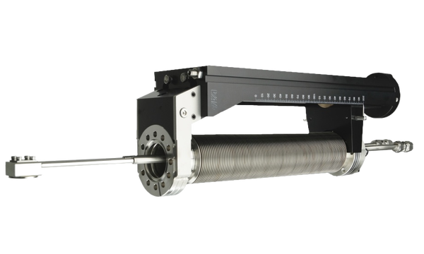
- Bayard-Alpert type ionization gauge
- Compatible with AML gauge controllers
- Mounting flange DN40 CF (O.D. 2.75")
- Linear gauge head positioning
- Standard linear travel 150 mm
- Bakeable up to 250°C Datasheet
Introduction
In many MBE applications the beam equivalent pressure (BEP) of the atomic or molecular beams from effusion cells can be used to determine flux ratios and growth rates near or at the sample position. Our Beam Flux Monitor BFM has been designed and optimized for this purpose.
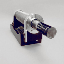
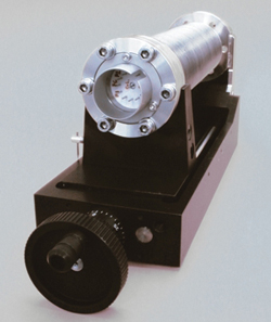
The basic component of the BFM is the Bayard-Alpert type ionisation gauge, that is mounted on a linear motion feedthrough with edge-welded bellows. By means of this feedthrough, the gauge can be shifted linearly between a measurement- and a standby-position.
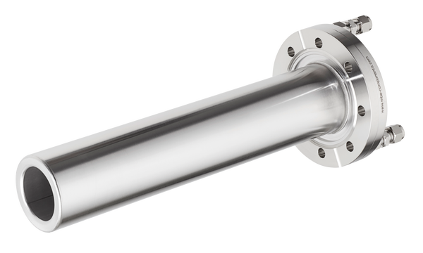
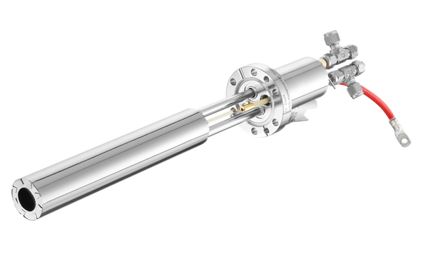
The design of the BFM includes the shielding of the gauge head, inhibiting contamination of a substrate behind the gauge head during flux-monitoring. The shielding parts can be seen on the right hand figure.
Application
Typical applications for the BFM beam flux monitor are:
- flux calibration of effusion cells vs. source temperature
- fast check of flux ratios from different sources before growth (e.g.
As/Ga in III-V MBE)
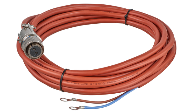
The BFM series has been designed to be pin-compatible with ion gauge controllers of the PGC-series from AML. The electrical 12-pin feedthrough of the BFM mates with a standard AML gauge head connection cable. If other ion gauge controllers shall be used, adaptability to the pin-out shown on the left and match with the characteristics of the ion gauge head (see below) is required.
Ion Gauge Head Specifications (when used with AML controller):
Bayard-Alpert type ionization gauge measurement principle
10 -3 mbar to 4x10 -11 mbar pressure range
sensitivity 17 mbar -1 (for N 2 )
X-ray limit 4x10 -11 mbar
ceramic/metal isolator base
filaments: 1x tungsten, 1x thoriated iridium
filament voltage 6 to 20 V
emission current max. 10 mA (100mA tungsten, 60 mA, thoriated iridium)
filament bias +50 V (+0 V during e-bombardment degas)
collector voltage +0 V
grid voltage + 200 V (+500 V during e-bombardment degas)
| Mounting flange | DN40 CF (O.D. 2.75") [mm / inch]; port I.D. >= 38 mm |
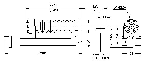
| Dimensions | ( L x W x H ) 380 x 94 x 105 mm (BFM 40-150) |
| In-vacuum length | 123 mm retracted / 273 mm extended (BFM 40-150) |
| Linear travel | 150 mm standard, other on request |
| Bakeout temperature | up to 250 °C |
| Controller | AML PGC-series or compatible; other (e.g. Granville-Phillips) on request |
| Electrical connectors | pin-compatible with AML controller cables |
| Measurement range | 10 -3 mbar to 4x10 -11 mbar total pressure or BEP |
| Degas principle | electron bombardment |
Dimensions
