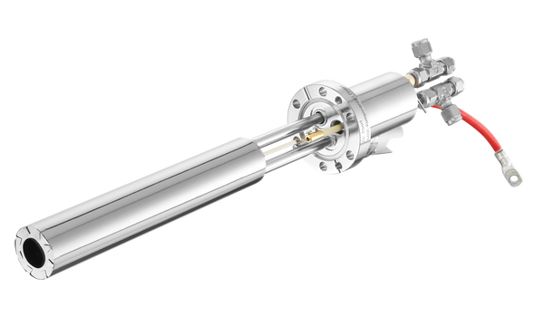
- Provides sulfur flux rates for R&D applications on a DN40CF flange
- Flux regulation and on/off control by motorized valve
- UHV-tight valve
- Water-cooled cracker with beam shaping nozzle
- 150 cm³ reservoir
- Reservoir and valve are located ex vacuum Datasheet
Introduction
The Valved Sulfur Source VSS aims at R&D applications where valve controlled small or medium flux rates of high vapor pressure materials are required.

This cell comes with a water-cooled cracker that reaches temperatures up to 1400°C. The cracker and injector building blocks are identical with our established TCC design. As shown for TCC, the thermal cross talk between the cracker and reservoir are almost negligible. See figure on the right for a schematic overview of the VSS cell.
The reservoir and the valve are both located ex vacuum. This offers a huge benefit for reloading the reservoir or maintenance work, which can be done without venting the chamber. The reservoir and valve are heated by industrial grade electrical heaters and are both temperature controlled with high accurate Pt100 thermometers. In order to achieve the highest possible cleanliness all critical welds for the valve and reservoir are prepared by electron beam welding.
 Schematic of VSS
1 case, 2 vacuum chamber
3 stepper motor for valve regulation
4 material reservoir, 5 valve
6 PBN injector tube, 7 cracker insert, 8 shutter
9 electrical heater, 10 water cooling
The VSS is designed for reservoir temperatures up to 250°C and works smoothly down to 100°C. The internal thermal design ensures ideal temperature gradients for trouble free operation. To ensure maximum process control this cell offers four independent heating circuits (reservoir, valve, pipe, cracker). However, depending on application the cell can be operated by using three circuits only .
The VSS is equipped with a high precision stepper motor that controls the valve. Hence, flux modulations in the order of two magnitudes are typically obtainable. For other applications pneumatic and manual valve control is also available.
There are two different valve types available for the VSS, namely a high throughput variation with higher overall throughput and one valve with smaller throughput but finer flux regulation characteristics. See the figure on the right for information about valve characteristic.
Application

A source concept like this is used for high vapor pressure materials, which form atom clusters. Typical evaporation elements are S and Se.
The in-vacuum length of the VSS is either 220 mm or 287 mm. Other in vacuum lengths are achievable using application specific spacers.
By default the cracker insert will be made from pyrolytic boron nitride, which will ensure efficient cracking for sulfur and selenium.
The following figure shows an example of a short operating cycle of the VSS.
| General | |
| Mounting flange | DN40CF (O.D. 2.75") |
| In-vacuum length L | 220 mm or 287 mm |
| In-vacuum maximum total length TL | 240 mm or 307 mm |
| Maximum airside length OL | 459 mm |
| In-vacuum diameter D | 36 mm |
| Maximum airside radius AR | 300 mm |
| Shutter distance DS | 15 mm |
| Shutter opening angle | 90° ccw |
| Bakeout temperature | 200°C |
| Cooling water flow | 30-90 l/h |
| Weight | 13 kg |
| Maximum chamber pressure | 10-5 mbar |
Reservoir | |
| Heater type | Industrial grade electrical heater |
| Temperature sensor | Pt100 class A |
| Operating temperature | 100°C – 245°C |
| Outgassing temperature | Up to 300°C |
| Cooling | None |
| Reservoir capacity | 150 cm3 |
| Reservoir material | Stainless steel or Inconel |
Valve | |
| Heater type | Industrial grade electrical heater |
| Temperature sensor | Pt100 class A |
| Operating temperature | 100°C – 295°C |
| Outgassing temperature | Up to 300°C |
| Cooling | None |
| Valve material | Stainless steel |
Tube | |
| Heater type | Ta wire filament |
| Thermocouple | W5%Re/W26%/Re (type C) |
| Operating temperature | 200°C – 600°C |
| Outgassing temperature | Up to 600°C |
| Cooling | None |
| Tube material | PBN |
Cracker | |
| Heater type | Ta wire filament |
| Thermocouple | W5%Re/W26%/Re (type C) |
| Operating temperature | 300°C – 1000°C |
| Outgassing temperature | Up to 1200°C |
| Cooling | Integrated water cooling shroud |
| Cracking insert material | PBN or graphite |
Dimensions

Specific data
For general information on CF mounting flanges see Flange and Gasketdimensions .
| Product | CF flange | Nominal capacity | Reservoir outer diameter | Cooling | Shutter* | Valve type | Valve control | UHV dimensions*** [mm] | max. electrical [W]/[A] | Power supply product code | |
|---|---|---|---|---|---|---|---|---|---|---|---|
| [cm3 ] | [mm ] | [mm]/[mm] | [W]/[A] | Product code | |||||||
| VSS | 40 - | 150 - | 51 - | K | S - | RV - | MC - | LxxxD36 | reservoir 80/2 valve 80/2 tube 100/5 cracker 150/8 | PS 60-35 PS 60-35 PS 36-12** PS 36-12 | |
| VSS | 40 - | 150 - | 51 - | K | S - | RV - | HC - | LxxxD36 | reservoir 80/2 valve 80/2 tube 100/5 cracker 150/8 | PS 60-35 PS 60-35 PS 36-12** PS 36-12 | |
| VSS | 40 - | 150 - | 51 - | K | S - | TV - | PC - | LxxxD36 | reservoir 80/2 valve 80/2 tube 100/5 cracker 150/8 | PS 60-35 PS 60-35 PS 36-12** PS 36-12 |
* rotary shutter possible on same flange (option S) ** optional *** specify UHV length L with order (L=220 mm or L=287 mm)
Typical accessories
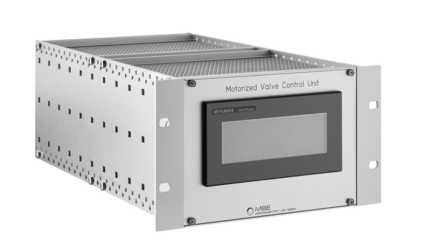
- Motorized Valve Control Unit MVCU
- Rotary Shutter Module RSM
Product code: e.g. VSS 40-150-51-KS-RV-MC-L220D36 is a valved sulfur cracker source on DN40CF flange with 150 cm³ nominal reservoir capacity, integrated cooling shroud and shutter, fine regulation valve and motorized valve control, in-vacuum length 220 mm and outer diameter 36 mm.


