VACS
Valved Arsenic Cracker Source
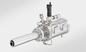
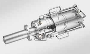
VACS 100-300 valved arsenic cracker with DN63CF (O.D. 4.5") mounting flange (using a VADP 100-63 adapter), 300 cm³ crucible, cooling shroud and motor drive
-
Compatible with all MBE systems
-
Crucible capacity 300 cm³, 500 cm³ or 2000 cm³
-
Large valve opening
-
Precise and very fast flux control
-
Easy handling and refilling procedure
-
Integrated water cooling shrouds
|
The Valved Arsenic Cracker Source VACS is designed for high performance growth of III-V materials. |
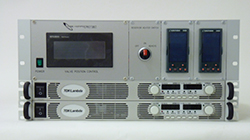 Motorized Valve Control Unit MVCU with motor drive for VACS 100-300 and VACS 100-500 |
|
The valve unit can be operated manually or with an additional valve control unit (MVCU) which controls the valve position by an external analogue voltage (0...10V), see picture on the right. |
 |
|
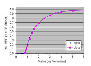
The typical valve characteristic, i.e. the beam equivalent pressure (BEP) as a function of the valve position, is shown on the right. The graph indicates the wide flux range of more than two orders of magnitude which is smoothly controlled on a wide value position range of several millimetres, when operated with a MVCU. The MVCU has a spatial resolution of 1/100 mm. This smooth operation condition guarantees a precise and reproducible flux control for your application. Together with a high motor speed of 10 mm/s a fast control is reached. |
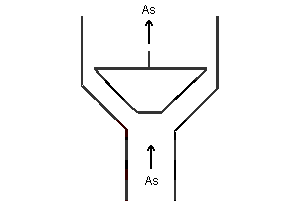 Schematic illustration of the VACS valve design |
|
The VACS has proven to be a very reliable As source in the field. It is compatible to commonly used industrial and research MBE systems. |
 VACS 150-2000 with 2000 cm3 crucible capacity for industrial applications with DN125CF (O.D. 6.75") mounting flange (using a VADP 150-125 adapter). |
ApplicationThe VACS is used for As4 or As2 sublimation in III-V MBE.Large crucible capacity (300 cm³, 500 cm³ or 2000 cm³), fast and precise flux control and easy handling for maintenance and crucible refill make the VACS ideal for smaller production MBE systems as well as for higher throughput research MBE systems. |
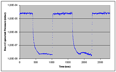 BEP vs. time, with valve on and off (cell temp. 390°C / cracker temp. 600°C). The motorized valve control allows to adjust and switch the As2 flux within seconds within about 3 orders of magnitude |
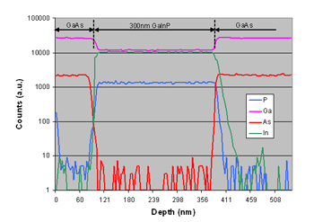 SIMS of GaInP on GaAs buffer layer on (100) GaAs substrate with VACS and VGCS applied |
| Very sharp transitions of As are achieved by application of VACS and VGCS sources at one deposition run. 300 nm GaInP are deposited on a GaAs buffer layer on a (100) GaAs substrate. Due to the fast flux control properties of the valve unit the As concentration in the GaInP layer is at its detection limit, i.e. three orders of magnitude below the GaAs level, which is demonstrated by the top right SIMS measurement. In return, P is sharply reduced on the GaInP/GaAs interface. |
Technical data
| VACS 100-300 / VACS 100-500 | VACS 150-2000 | |
| Filament type | 2 separate heater-circuits (reservoir/cracker) |
3 separate heater-circuits (reservoir/valve/cracker) |
| Thermocouple | W5%Re/W26%Re (type C); 2 thermocouples (cell/cracker) |
W5%Re/W26%Re (type C); 3 thermocouples (cell/cracker) |
| Operating temperature | reservoir: 300-450°C; cracker: 500°C (As4-mode) - 1100°C (As2-mode) |
reservoir: 300-450°C valve: 320-470°C cracker: 500°C (As4-mode) - 1100°C (As2-mode) |
| Outgassing temperature | reservoir: 500°C; cracker: 1200°C |
reservoir: 480°C valve: 500°C cracker: 1200°C |
| Bakeout temperature | 250°C | 250°C |
| Cooling | integrated water cooling shrouds | integrated water cooling shrouds |
| Crucible | 300 cm³ or 500 cm³ | 2000 cm³ |
| Flux control |
integrated valve unit | integrated valve unit |
| Valve control | hand control, or motor drive with control unit MVCU | hand control, or motor drive with control unit MVCU |
| In-vacuum dimensions |
L=360 mm - AL D, SL = customer specific ID=33 mm / 38 mm |
L=360 mm - AL D, SL = customer specific ID=38 mm |
| Airside dimensions |
AL= customer specific OL=290 mm / 375 mm AR= 208 mm |
AL= customer specific OL=566 mm AR= 260 mm |
| Weight |
22 kg | 45.5 kg |
Dimensions
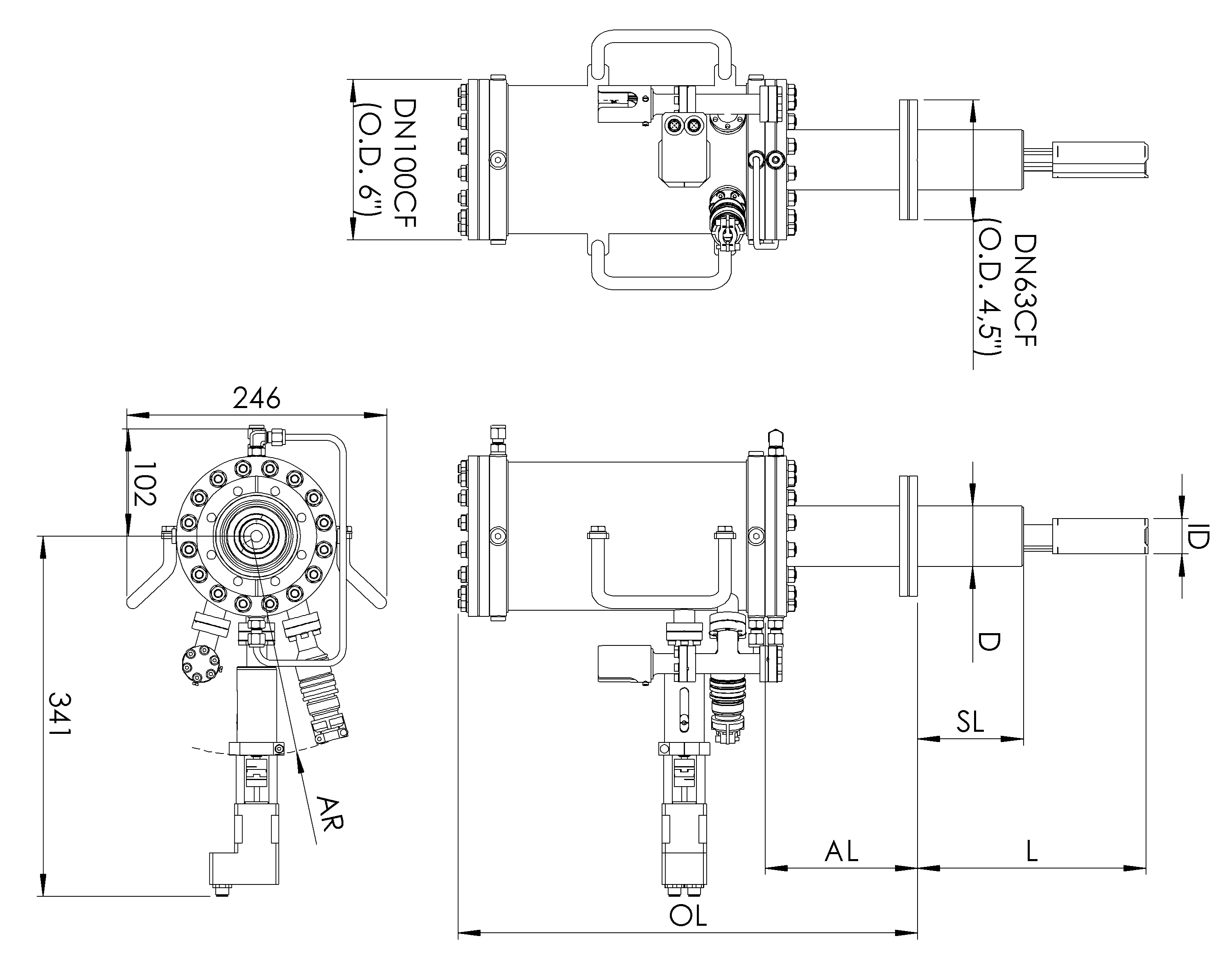 |
Schematic drawing of the Valved Arsenic Cracker Source VACS (drawing shows VACS 100-300 with VADP adapter) |
Specific data
For general information on CF mounting flanges see Flange and Gasket dimensions.
 |
 |
 |
 |
 |
||
|---|---|---|---|---|---|---|
| [cm3] | [mm] / [mm] | [W] / [A] | Product code | |||
| VACS | 100* - | 300**- | LxxxD57 | cell: 200 / 6 cracker: 300/ 10 |
2x PS 70-10-C | |
| VACS | 100*- | 500**- | LxxxD57 | cell: 300 / 6 injector: 300 / 10 |
2x PS 70-10-C | |
| VACS | 150*- | 2000**- | LxxxD89 | reservoir: 300 / 6 valve: 200 / 6 cracker: 300 / 10 |
3x PS 70-10-C |
| * | other mounting flange diameters feasible in combination with VADP adapter flanges (on request) |
| ** | other capacities on request |
| *** | specify UHV length L with order |
Product code:
e.g. VACS 100-300-L290D57
is a valved arsenic cracker source on DN100 CF flange with 300cm³ crucible capacity and UHV-length 290mm.
Related products
The following list provides suggestions for related products. For additional product suggestions or more detailed information, please contact us.
Components
 |
 |
|
| Thermal Cracker Cell TCC |
Valved Thermal Cracker Cell VTCC |
Accessories
 |
 |
|
| Motorized Valve Control Unit MVCU |
Beam Flux Monitor BFM |
Systems
 |
 |
|
| OCTOPLUS 400 | OCTOPLUS 600 |
